Usage
The board ships with everything ready to go - preloaded with firmware to start flashing right away. Even the microSD card is preloaded with bin files for trigBoard release (11/29/21)
Board Power
Can just connect a micro USB cable to the board or a 4.2V lithium battery (CHECK POLARITY), any of the adafruit batteries will work. Note that the board can also charge the battery - the charge LED indicates status red-charging, green-complete
- Target Power
The board has a PH-2 JST connector that can be used to power the target ESP32. There are 4 power sources for this connector selected by jumper:
3.0V is a switched power source that the board can turn on/off on-demand. Very useful for power cycling the target and since it’s 3.0V, can be used for calibration. RECCOMENDED
5V always on from USB, or boosted if running on battery
3.3V always on
VBAT is the raw battery voltage
Files
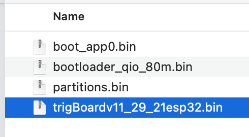
When you upload from the Arduino IDE, it flashes x4 bin files. One of these is the actual firmware, while the other 3 are mostly going to be the same for most applications. You can use the stock files that are on the microSD card, and only replace this file:
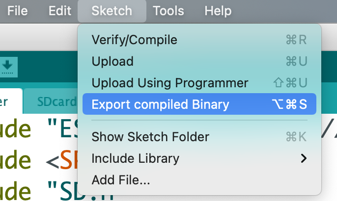
You can generate this file yourself by “Export Compile Binary” from the Arduino IDE:
- The ESPprogrammer will automatically find all of these files by their names, so don’t worry about renaming.
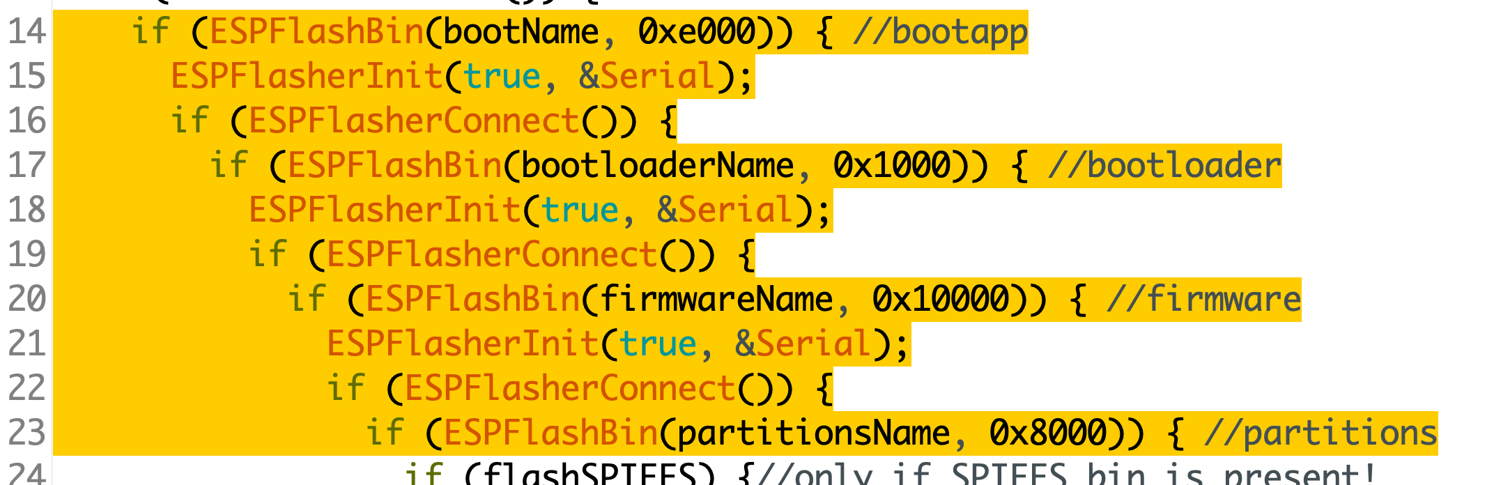
This is how it finds these files:
const char bootKey[] = "boot_app";
const char bootloaderKey[] = "bootloader";
const char partitionsKey[] = "partitions";
const char firmwareKey[] = ".ino.bin";//when you flash over USB, it looks like this
const char firmwareSecondKey[] = "esp32.bin";//when you export compiled binary, this is the file it generates
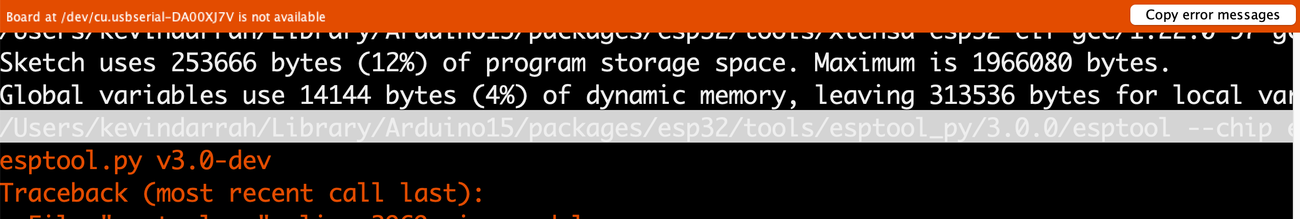
Those other three bin files can also be updated, since these are generated when their are updates to the ESP32 core or if any of the board settings are changed. From the IDE, make sure Verbose output is enabled, then when you try to upload via USB (even if a board isn’t connected), you want to copy this last command out:
Paste that into text editor and you’ll see the paths to all 4 bin files:
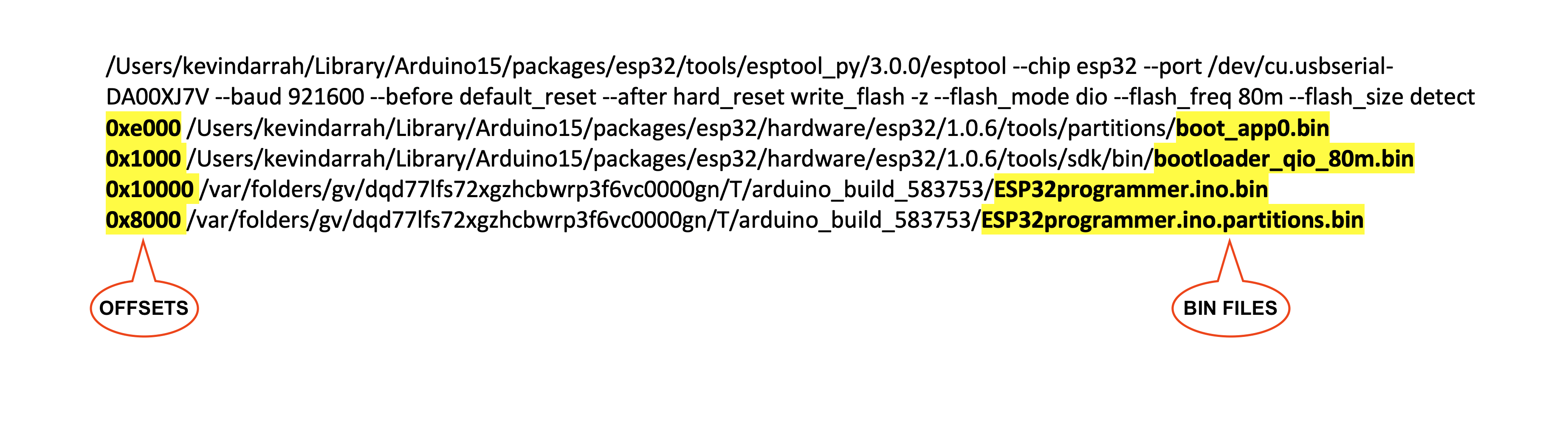
You can navigate to these folders and COPY them to the microSD card.
NEW FOR BOARDS SHIPPED AFTER NOV 2023 There is now a config.txt file on the sd card that can be used to set the programming offsets to anything you want. Useful for programming different variants of the ESP32, like the S3, C3, etc.. This file is very sensitive to spaces and formatting, so be careful when changing this.
Here is an example for an ESP32
bootNameOffset=0xe000
bootloaderNameOffset=0x1000
partitionsNameOffset=0x8000
firmwareNameOffset=0x10000
spiffsNameOffset=0x3D0000
Here is an example for an ESP32-S3
bootNameOffset=0xe000
bootloaderNameOffset=0x0
partitionsNameOffset=0x8000
firmwareNameOffset=0x10000
spiffsNameOffset=0x10000
THIS IS JUST HERE FOR REFERENCE, but all boards shipped before Oct 2023, have the these offsets hard coded Also, note the offsets above. These can change depending on your partition scheme, so double check your settings and note that you may have to also change the ESP programmer code. *THE PARTITON SCHEME USED HERE IS “Minimal SPIFFS(1.9MB APP with OTA/190KB SPIFFS)”*
Connections
All signals are 3.3V! regardless of target power setting
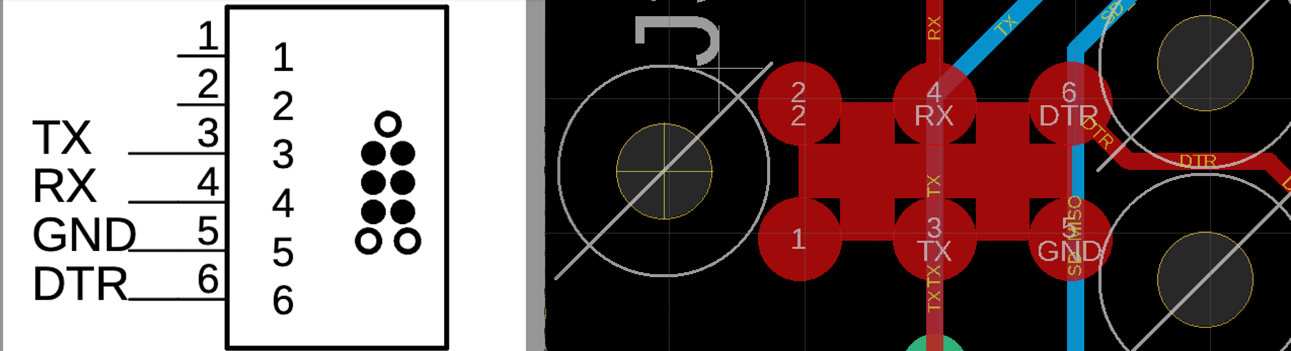
The female 1x6 connector follows a standard FTDI pinout, where the DTR pin is controlled by the board to trigger the auto-reset circuit, but if your target board doesn’t have an auto-reset circuit, then you’ll have to toggle reset/gpio0 on the target to place in download mode. The other way that I’ve tested the board with targets that don’t support an auto reset circuit is to let programmer just cycle power, and connect the DTR pin to the Boot pin on the target - tested this on ESP32-S3 and -C3 customer boards. Just note that this is with the jumper in the 3V position since this is the “switched” power from the programmer.
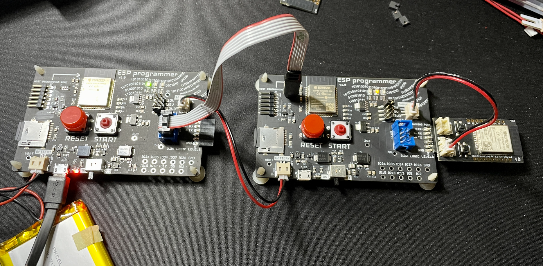
The 2x6 was intended to be used with Tag Connect Cables
You’ll notice that even the programmer board uses this style interface, so technically programmer board can upload to another programmer board!!
For reference, the supporting pinout on the target board:
Flashing
Files loaded on microSD card?
Target Power set?
Target board connected?
Programmer board has power?
Slide the switch to ON, wait for GREEN LED?
PRESS Green Button, and should see the YELLOW LED start flashing, when you see the GREEN LED flash, then you know everything is working. Eventually, you’ll see the only the GREEN LED flash, and you’re done!
NOTE: If you see the RED LED turn on, this means something went wrong and will have press the RESET button to start over. You can connect to the HOST Programming port with a USB-Serial converter to debug what went wrong.
Clone Board/Copy SPIFFS
A lot of ESP32 projects will use SPIFFS to store various settings/parameters. All customizable features in the trigBoard are stored in SPIFFS, so if you had one “golden” board that you had setup (WiFi/Push Notification Settings/etc), then you can also create a separate bin file that contains this information as well. Otherwise, when you flash only the 4 files as described above, the SPIFFS remains as-is. So if you’re flashing a fresh device, the SPIFFS will be blank…. or maybe you want to erase the SPIFFS as well? This is possible with this same technique.
STEP 1 - READ FROM GOLDEN BOARD You will need to use the command line/terminal with a USB-Serial converter connected to the “Golden” ESP32. Will be using MacOS for this walkthrough, though should be similar on Windows.
Fastest way to get going with this is to use the Arduino IDE as if you’re programming an ESP32. Connect the USB-Serial converter, choose the com port, and without the ESP32 connected, try uploading a blank sketch. It will obviously fail but this is what we want. Now you can copy out the command used to flash the board:
We’re not going to flash, but instead, we’re going to read the flash. This sets up the command for us, so you’ll start with something like this from the Arduino IDE:
/Users/kevindarrah/Library/Arduino15/packages/esp32/tools/esptool_py/3.0.0/esptool --chip esp32 --port /dev/cu.usbserial-DA00XJ7V --baud 921600 --before default_reset --after hard_reset write_flash -z --flash_mode dio --flash_freq 80m --flash_size detect 0xe000 /Users/kevindarrah/Library/Arduino15/packages/esp32/hardware/esp32/1.0.6/tools/partitions/boot_app0.bin 0x1000 /Users/kevindarrah/Library/Arduino15/packages/esp32/hardware/esp32/1.0.6/tools/sdk/bin/bootloader_qio_80m.bin 0x10000 /var/folders/gv/dqd77lfs72xgzhcbwrp3f6vc0000gn/T/arduino_build_3054/sketch_feb27a.ino.bin 0x8000 /var/folders/gv/dqd77lfs72xgzhcbwrp3f6vc0000gn/T/arduino_build_3054/sketch_feb27a.ino.partitions.bin
Let’s change that to this:
/Users/kevindarrah/Library/Arduino15/packages/esp32/tools/esptool_py/3.0.0/esptool --chip esp32 --port /dev/cu.usbserial-DA00XJ7V --baud 230400 read_flash 0x3D0000 0x30000 spiffs.bin
- Couple things I changed there:
Slowed the baud rate slightly for reading - this has just been more reliable for me
The command is now read_flash
The 0x3D0000 in there is the offset for the SPIFFS Based on your partition scheme In my case, again I used “Minimal SPIFFS… ” But if you change this, you can look it up here
The second number there 0x30000 is the size, which is also defined by the partition table.
For example, when you pull up the *min_spiffs.csv* from that link, you can see the two numbers you’ll need for this scheme:
What if you want to erase the SPIFFS? Well, just run this command before you read the flash:
/Users/kevindarrah/Library/Arduino15/packages/esp32/tools/esptool_py/3.0.0/esptool --chip esp32 --port /dev/cu.usbserial-DA00XJ7V erase_flash
Now you have an easy way for the programmer board to erase the SPIFFS as well if you want as well.
STEP 2 SETUP PROGRAMMER BOARD
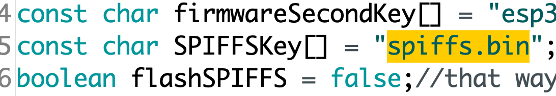
The latest ESPprogrammer code supports SPIFFS programming as well, so if it finds a file on the sd card “spiffs.bin”, then it will use that to flash the SPIFFS with this file. Otherwise, will only flash the 4 required files.
NOTE,just like the other 4 files, the offset in the code must match the partition scheme used, so you may have to change this code for your programmer:
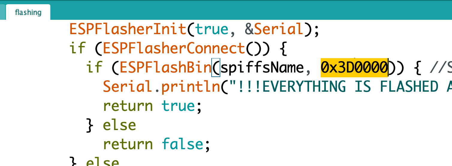
So if you’re also using the minimal SPIFFS scheme, then just copy the spiffs.bin file to the sd card and you’re good to go.
STEP 3 Calibration
The trigBoard also stores a factory calibration constant for the battery voltage measurement, so if you copy the SPIFFS from one trigBoard to another, you will also be copying the WRONG constant. No big deal though, you’ll just need to recalibrate the new board. Luckily, the programmer board provides an accurate 3V source, so if you have the jumper set to 3V and you’re power the board from this source, then just launch the configurator, scroll all the way down and make sure the calibration constant is set to 0. Then you can scroll back up and see the difference away from 3.0V the board is. Like if you see 3.5V, scroll back down and set the calibration to -0.5. Simple as that!